Images courtesy of BUTTING
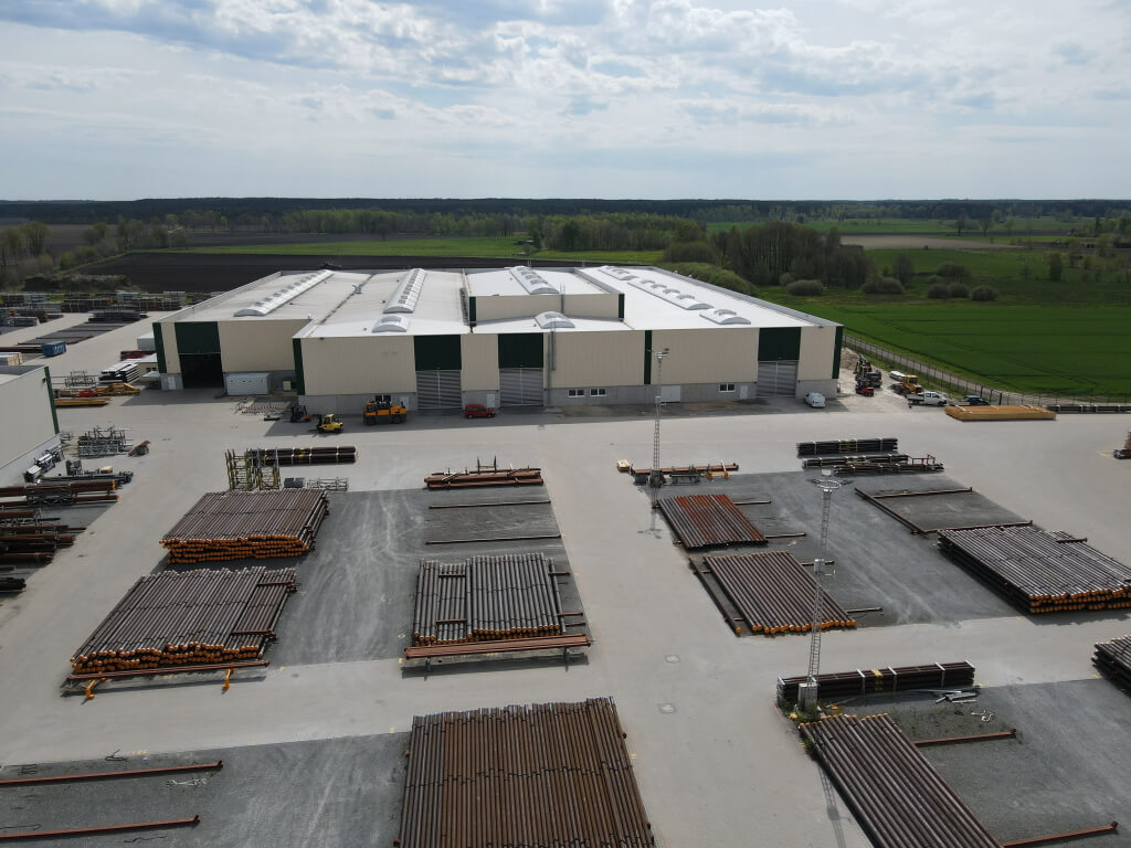
For over 240 years, BUTTING has produced high-quality piping products for demanding applications. Its mechanically lined BuBi® pipes have been employed successfully in some of the toughest areas of the oil and gas industry since the 1990s. To date, more than 1,500 km of BuBi® pipes are installed and successfully operating worldwide. BUTTING runs two production lines for 12m mechanically lined pipes with more than 350 km annual output. This high production capacity translates into short delivery times and tailor-made solutions for its global customers base.
By Joanne McIntyre
Since 1994, BUTTING has produced mechanically lined BuBi® pipes for the offshore and onshore oil and gas industry. The main applications are subsea flowlines and riser pipes, including in difficult areas like Steel Catenary Risers (SCRs) and lazy wave risers. Since the invention of mechanically lined pipes (MLP), this product has undergone rapid development to optimise product quality. Today these pipes are ideally suited for various pipe-laying methods, e.g. conventional methods like S-lay, J-lay and bundle, and reel-lay techniques.
Steel Catenary Riser (SCR) pipes based on mechanically lined pipes were first installed in 2014, in the Guará & Lula Brazilian Pre-Salt oilfield. The BuBi® pipes were installed via the reel-lay method using internal pressure or increased liner thickness. DNV GL approved the mechanically lined BuBi® pipes for installation as flowlines and fatigue resistant risers using the reellay method. Very tight tolerances at the pipe end are required to achieve this. The suitability of BuBi® pipes for SCR was demonstrated through a qualification programme and reference order for the Brazilian market. Since then, BUTTING has successfully carried out further projects in Brazil: Sapinhoa Norte, Peregrino and Bacalhau, and pipes are currently being delivered for a fourth project. As a logical progression, after many years of development work, BUTTING brought their new GluBi pipe to market in 2019: a glued, mechanically lined pipe that can be installed using the reel-lay method. The innovative product was certified by DNV GL in 2019, under DNVGL-RP-A203 as a “Statement of Qualified Technology”.
The process

Mechanically lined BuBi® pipes are made according to API or DNV standards in various main steps: manufacture of the carbon-manganese outer carrier pipe, production of the CRA inner pipe, and assembly of both components.
The wall thicknesses and material combinations for the outer and inner pipe depend on the project-specific pressure and corrosion resistance requirements. The forming, longitudinal welding and full body annealing of the CRA inner pipe (liner) to reduce stresses developed during forming and welding are carried out on fully automatic specially designed production lines. Final full-body pickling and passivation removes scale and ensure corrosion resistance. The main production step is a hydraulic expansion of the whole pipe in one process. On completion of the hydroforming process, the spring back of the outer pipe creates a tight mechanical bond.
The subsequent production steps focus on preparing the pipe ends for later pipelaying. An automated welding technique applies a minimum of two layers of weld overlay material. Finally, computercontrolled machining is used to create a smooth surface and assure that a perfect transition from weld overlay to the liner is secured and all tolerances for wall thicknesses (in particular for the liner) and diameters are met.
Non-destructive testing
The main focus of non-destructive testing (NDT) of mechanically lined pipes is the weld overlay at the pipe ends. Testing methods include visual testing (VT), liquid penetrant testing (PT), ultrasonic testing (UT) and radiographic testing (RT). Various methods have been developed to test the transition zone between the weld overlay and the CRA liner (= triple point: carbon-manganese steel, liner, weld overlay) with the highest possible test sensitivity. Besides digital X-ray, special ultrasonic testing has also proven to be successful.
As part of the BUTTING Group, Hillger NDT develops advanced NDT technology for mechanically lined BuBi® pipes. Furthermore, BUTTING’s own reeling simulation system enables project-specific railing tests or extensive reeling qualifications for new solutions to be carried out. Besides mechanically lined BuBi® pipes, BUTTING offers metallurgically and weld overlay clad products as well as super duplex pipes and bends for subsea projects. BUTTING has proven to be the reliable solution provider in many projects globally and has become the global market leader in this segment.
Advantages of BUTTING mechanically lined pipes
• Tightest ID and out of roundness tolerances at the pipe ends
• Full package provider with excellent project management that reduces supply-chain risk in subsea projects
• Wide variety of material combinations
• Manufacturing of large quantities of pipes can be carried out economically with the largest capacity for MLP.
• Cost savings: Overall lowest installation costs are achieved in cooperation with the customer
• Distinguished competencies in NDT (Hillger NDT) to guarantee premium quality products


Precise laser measurement
Tighter tolerances play an increasingly important role for line pipes in the oil and gas industry. On the one hand, this allows further processing to be accelerated and costs reduced; on the other hand, pipes have to meet even greater requirements due to greater working depths. Dynamic loads and increasing pressures are the main issues here. This development has led to stricter pipe end tolerances and laser measurement technology being more frequently used to measure and document tolerances.
The key tolerances at the pipe end

Tolerances for wall thickness, squareness, inner or outer diameter, and ovality are measured at the pipe end. All values are quality characteristics defined in a specification such as DNV, API or a customer specification and have predefined values. For further processing by the pipe layer, the inner diameter tolerance and the ovality at the pipe end are particularly important to ensure problem-free and fast joining of the pipes at the construction site.
The inner diameter is defined as the circumference of the inner surface of the pipe divided by pi. There is only one value for the inner diameter per measurement in a circumferential plane, e.g. 10 mm from the pipe end. The ovality of a pipe end is calculated from the difference between the largest and smallest measured inner diameter value on a defined measuring plane. This absolute value is given in millimetres. Here, too, only one value results from a measurement.
In the case of extremely narrow tolerances, as required for steel catenary risers (SCR), both values can be combined. The requirement is then that the ovality is included in the inner diameter tolerance.
Example: ID tolerance = +/- 0.25 mm incl. ovality. Such tolerances can no longer be produced with conventional calibration of the pipe ends. These pipes are machined and turned so that the inside is circular. Today, laser measurement technology is used for checking compliance with the tolerance specifications.
Measurement methods at BUTTING

An important step in the inspection of pipes is determining the geometry of the pipe ends. There are many techniques and procedures for this. Some are simple and can be done manually (e.g. using callipers), others are far more complex and provide precise data about any point on a measured surface. Advanced measurement methods are required to obtain measurement results with good accuracy, i.e. high precision and low measurement deviation.
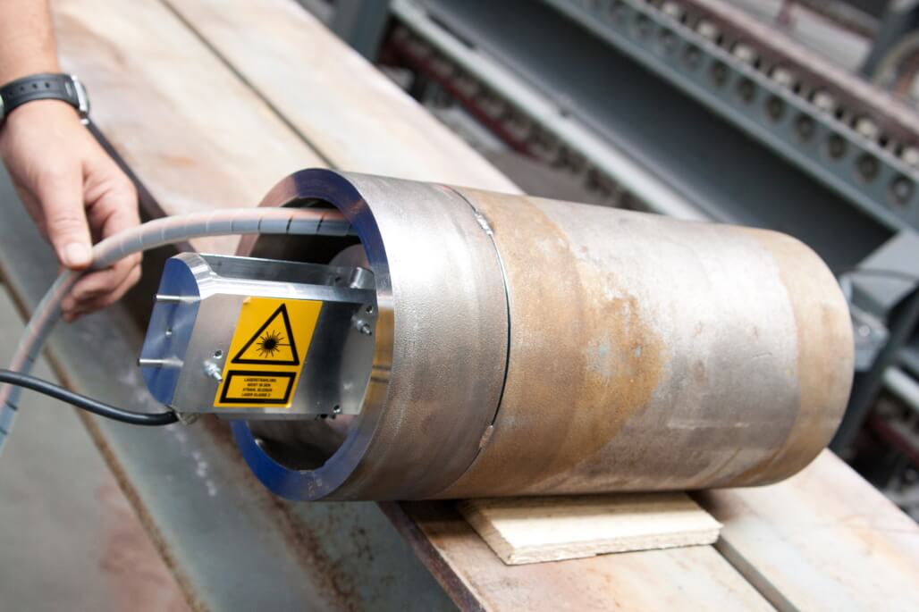
The pipe end measuring system used at BUTTING is based on laser technology using a point triangulation sensor. The laser is mounted on a rotatable axis, enabling a complete scan of the inner contour. Once positioned, the unit automatically makes a 360° rotation, and over 3,600 data points are collected for each pipe end in less than eight seconds. The measuring accuracy depends on the pipe diameter and varies from 0.01 mm for smaller pipe dimensions to less than 0.05 mm for larger dimensions. This measuring system enables up to 120 pipe ends to be measured during an 8-hour shift. The measurement data is processed using software, and the inner diameter and ovality are then determined. Non-contact measuring systems in the production line, such as the laser measurement process, offer significantly higher accuracy and reproducibility with less time required compared to manual measurement.
Influence of individual process steps on the ovality of a pipe
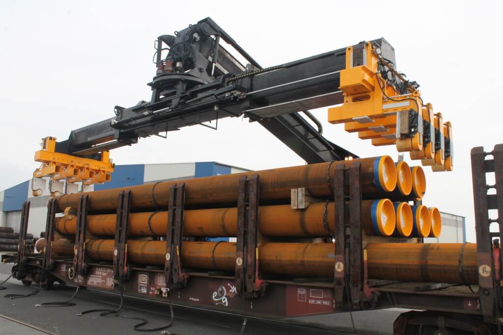
In addition to deciding how a measurement is to be carried out, it is also crucial to determine when a pipe is to be measured. Along the path from inspection in the factory to assembly, various process steps influence the ovality of a finished calibrated pipe. In particular, the mechanical stress that a pipe experiences during the loading process and transport can have a significant effect on its ovality. Experience shows that the ovality can change by 0.1 mm to 0.4 mm between the quality control carried out by BUTTING and final assembly. This value varies depending on the pipe diameter and wall thickness. For critical projects, BUTTING therefore recommends repeating measurements at the end of the process chain, directly before pipe laying.

Every week we share a new Featured Story with our Stainless Steel community. Join us and let’s share your Featured Story on Stainless Steel World online and in print.


