

In this article, Baher Elsheikh explores the fundamental mechanisms of SRC, compares Alloy 800H with stainless steel grades like SS347H in their susceptibility and response to SRC, and examines mitigation strategies under ASME Boiler and Pressure Vessel Code (BPVC) provisions as the main design code for pressure vessels and boilers in oil and gas industry and in nuclear applications as well.
By Baher Elsheikh, SABIC Agri-Nutrients
Stress Relaxation Cracking (SRC) is a significant failure mechanism in high-temperature applications of austenitic materials, which can occur in areas with high levels of tensile residual stresses, especially within the weld heat-affected zones (HAZ) or in cold-formed areas.
It is particularly prevalent in austenitic stainless steels and nickel-based alloys used in the fabrication of critical components like superheaters and reheaters in the petrochemical and power generation industries. Unlike traditional forms of cracking, like hot cracking or creep rupture, SRC develops during the relaxation of residual or applied stresses at elevated temperatures.
During fabrication, SRC may be called reheat or stress relief cracking; during service, it may be called creep embrittlement cracking, stress-induced cracking, and stress-assisted grain boundary oxidation cracking.
Special considerations
Addressing SRC in equipment and weld joints requires special attention for three key reasons.
Firstly, SRC is challenging to detect during its early stages. Yet, once it initiates, it often progresses rapidly to failure in a brittle manner, typically rupture, early in the equipment’s service life.
Secondly, SRC predominantly occurs in thick-walled components operating at elevated temperatures, which are typically used in critical, high-risk applications.
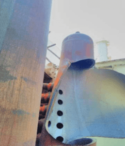
Thirdly, the current design codes, such as the ASME Boiler and Pressure Vessel Code (BPVC), do not fully account for all the factors necessary to prevent SRC. A recent report by the US Nuclear Regulatory Commission1 identified this as a significant gap in the ASME BPVC provisions. Figure 1 shows the rupture of a superheated steam coil outlet header, made from 48 mm thick SS316H, caused by SRC at the longitudinal seam weld. The rupture resulted in extensive damage within the convection section of the steam reformer at a methanol plant. Additionally, large fragments of debris were projected up to 100 meters across the site, impacting surrounding areas.2
Morphology and critical factors of SRC
SRC is an intergranular failure mechanism that may manifest as either surface-breaking or embedded cracks, depending on the stress state and component geometry. It is predominantly found in coarse-grained sections of the weld heat-affected zone (HAZ), though weld deposits can also exhibit SRC under certain conditions. Typically, cracks initiate at areas of stress concentration, and once formed, SRC may facilitate further propagation through fatigue mechanisms.
Three primary factors contribute to SRC:
1. Residual stresses
2. Susceptible microstructure
3. Elevated temperature in creep dominant regime10
Cracking happens without any gross plasticity, and most of the deformation is concentrated at grain boundaries. Alloys susceptible to SRC contain alloying elements that encourage the formation of fine intragranular precipitate particles, making the grains stronger than the grain boundaries. Consequently, creep deformation resulting from stress relaxation concentrates at the grain boundaries and eventually causes intergranular cracking.1 That is why stabilised grades of austenitic stainless steel, like SS347 and SS321, are more susceptible than SS304.3
Smaller grain sizes resist SRC better. Grain growth can be controlled by using lower solution annealing temperatures, achieving ASTM 4 or finer grains. Traditional heat treatment of austenitic alloys results in coarse grains (ASTM 5 and coarser), which improve creep resistance but also increase SRC risk after cold forming.3
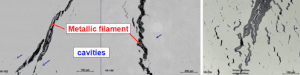
The cracks are always located on the grain boundaries, with small isolated cavities present in front of the cracks.
A metallic filament is mostly present on the cracked grain boundaries. This filament is enclosed by a chromium-rich oxide layer. The Ni and Fe contents are low in this oxide layer. The chemical composition of the metallic filament is material dependent, but always low in chromium and high in nickel (for 800 alloys) and iron (for SS alloys). See Figure 2 for typical crack morphology.


Applicable standards and guidelines
Although Stress Relaxation Cracking (SRC) is a well-recognised damage mechanism, current codes often lack specific guidelines to ensure that equipment designed in compliance with them is also protected against SRC and the risk of premature brittle failure. Let’s examine the most relevant standards and guidelines addressing SRC, highlighting their provisions and potential gaps in effectively managing this damage mechanism.
1. ASME BPVC SEC II Part D4
In non-mandatory Appendix A ‘Issues associated with materials used in ASME code construction’, paragraph A-206 addresses SRC that can occur in cold- or warm-worked austenitic materials when precipitation of temper-resistant particles occurs at defect sites introduced during mechanical working. When the material is exposed to intermediate temperatures (510°C to 760°C) during heat treatment or service, strain localises at the grain boundaries, leading to rapid intergranular creep cracking.
The code highlights that this phenomenon has led to through-wall failures in pressure parts made from susceptible heats of materials like 347H and 310HCbN, even during heat-up for solution annealing. To reduce the risk of such failures, ASME has introduced rules in PG-19 (Section I) and UHA-44 (Section VIII, Division 1), specifically aimed at mitigating SRC risks during design and fabrication.
This inclusion confirms that SRC is recognised and partially addressed within the ASME Code framework, though additional design-specific considerations may still be necessary.
2. ASME BPVC SEC VIII Div.15
In Non-mandatory Appendix UHA-A, paragraph UHA-A-4 acknowledges that stress relaxation cracking (SRC) may develop in P-No. 8 materials, not only in cold-formed areas but also in weld zones where high residual tensile stresses are present. To minimise this risk, the code advises applying post-weld heat treatment (PWHT) in accordance with Table UHA-44, unless specific criteria are met, such as when the design temperature is below 1000°F (540°C) or the welding is limited to low-risk configurations (e.g., circumferential welds or fillet welds with a thickness of 13 mm or less, or specific fin welding scenarios under tightly defined limits). This reflects the code’s recognition of SRC and its efforts to provide guidelines for mitigating it during design and fabrication.
It’s important to highlight that Table UHA-44 recommends solution annealing as the heat treatment method for relieving stress in cold-formed parts that exceed allowable fibre elongation. For example, the minimum recommended heat treatment temperature for SS347H is 1095 °C.
Meanwhile, in the mandatory portion of the code, Table UHA-32-3 outlines PWHT requirements for P-No. 8 materials and states that PWHT is neither required nor prohibited, effectively deferring the decision to the user, guided by non-mandatory Appendix UHA-A. This creates a grey area in the code, possibly due to the fact that PWHT itself can introduce SRC under certain conditions, in addition to increasing the risk of sensitisation in austenitic materials.
By contrast, the treatment of Alloy 800 series materials (UNS N08800, N08810, N08811) is more explicit. Paragraph UNF-56(d) mandates PWHT at 885 °C when the design temperature exceeds 540 °C, providing a clear preventive measure against in-service SRC. Notably, design software tools typically account for such conditional requirements, whereas manual design calculations might overlook them—posing a risk of noncompliance or design oversight.
3. ASME BPVC SEC I6
ASME Section I presents similar guidance to that of Section VIII, Division 1 regarding post-weld heat treatment (PWHT) for P-No. 8 materials. According to Table PW-39-8, PWHT is neither mandated nor prohibited. However, Note (b) in the same table suggests that PWHT may be advisable to mitigate the risk of stress relaxation cracking (SRC), particularly for thick sections operating at elevated temperatures, aligning with the recommendations in ASME Section II, Part D, Non-mandatory Appendix A. Ultimately, as in Section VIII, the decision is left to the user’s discretion, based on the specific service conditions and fabrication details.


4. API RP 5717
In API RP 571, SRC is discussed as a damage mechanism in Paragraph 3.54. It identifies susceptible materials, including austenitic stainless steels (304H, 316H, 321, 347) and nickel-based alloys (Alloy 800H, 800HT, 617). SRC typically occurs in the 500–750°C range and is influenced by grain size, material composition, weld strength, residual stresses, section thickness, and fabrication conditions. Large grain sizes and high residual stresses, especially in thick sections, increase SRC risk. The RP also notes that stress relief or stabilisation heat treatments can sometimes worsen SRC.
5. API TR 942A8
This API technical report addresses material selection, fabrication, and repair concerns for hydrogen and syngas reformer furnace outlet pigtails and manifolds. It highlights SRC as a major failure mode in these components when exposed to fabrication and operating temperatures between 500°C and 750°C.
The technical report includes a case history in a hydrogen reformer, where the inlet pigtail assembly combining Alloy 800HT and 304H stainless steel experienced through-wall cracking after three years of service at 593 °C (Figure 3). The failure occurred at the transition between the Alloy 800HT section and a 2¼Cr-1Mo steel weld, where stress concentration was high.
A metallurgical analysis revealed intergranular cracking with a nickel-rich path characteristic of SRC. Although stress relieving or solution annealing at 885 °C could mitigate SRC, it wasn’t feasible due to the proximity to the 2¼Cr-1Mo steel weldolet. Recommended alternatives included using fine-grained Alloy 800 or higher chromium alloys and modifying the geometry to reduce stress concentration.
6. API TR 942B9
This report examined Stress Relaxation Cracking (SRC) in austenitic alloys used in high-temperature refinery services, detailing its causes, susceptibility, and prevention. It ranked alloy susceptibility as: 800HT > 347 SS > 800H > 321 SS > 304 SS > 316 SS (higher susceptibility in alloys with fine intergranular precipitates).
It states that finer grains (ASTM 3.5+) resist SRC; ≥2% cold deformation increases risk, mitigated by 980°C stabilisation heat treatment. Mitigation strategies are:
- Welding: minimise restraint, avoid stress concentrations, and use low heat input techniques;
- Heat treatment: PWHT (843°C to 899°C) or multistep treatment (stress relief → solution annealing → stabilising at 593°C); and
- Material considerations: limit Bismuth (Bi≤0.002%) in Type 308 FCAW weld metal for temperatures 538°C.
API TR 942B recommends the application of PWHT for some austenitic SS grades and at temperatures quite different from those advisable by ASME BPVC. For example, the recommended PWHT temperature for SS 347 is 900 °C (1hr / 25 mm, 3 hours minimum), followed by still cool air.
Case histories
The following are two case histories for two of the most vulnerable materials to SRC; alloy 800H and stainless-steel grade 347H.
1. Cracking of Alloy 800H reformer riser12
A failure occurred in a steam reformer riser where a cast HP Micro Alloy riser tube was welded to an alloy 800H transition piece. While the first incident in 2010 was caused by thermal shock from a water leak, further inspections revealed multiple cracks in the heat-affected zones of the 800H welds not linked to water damage. This prompted a detailed investigation.
The cracking showed classic signs of Stress Relaxation Cracking including:
- Intergranular cracks in the HAZ
- Voids and grain boundary oxidation
- Nickel-rich metallic filaments with chromium-depleted zones
- Cracking in areas with hardness near 200 HV
- Occurrence within 1–2 years of service at around 600°C
The design had been modified in 2006, moving the weld joint location closer to a cooler area near a water jacket. This location likely created the ideal conditions for SRC: high residual stress, coarse grains, and operating temperatures within the critical 500–750°C range.
The solution was to perform post-weld heat treatment (PWHT) at 885°C, which relieved stress and reduced hardness. After this treatment, no further cracking was observed, confirming that SRC was the root cause. This is the recommended heat treatment condition in ASME BPVC sec VIII div.1 para UNF-56 as explained earlier in this article, and is an example of how such requirements can be missed. This case clearly illustrates how SRC can silently damage high-temperature components and the critical role of heat treatment in preventing it, even in austenitic alloys like 800H, which were once thought to be immune.


2. Cracking of SS 347H pipe at inlet of steam reformer13
Inlet piping of a steam reformer fabricated from SS 347H failed at the welded support pad. Cracking occurred in less than 16 months. The failures were observed in welded reinforcing pads and branch connections of inlet pipes. Notably, no Post-Weld Heat Treatment (PWHT) had been applied. Key features of SRC observed included:
- Intergranular cracks originating at grain boundaries.
- Nickel-rich metallic filaments surrounded by chromium-rich oxide layers.
- Cavities and signs of localised embrittlement.
- Hardness >200 HV at crack locations with no visible plastic deformation.
Corrective actions included:
- Replacing welded supports with clamp-type supports to reduce restraint.
- Applying PWHT at 875–930°C to relieve residual stress and reduce hardness.
- Improving insulation to prevent sensitisation and external corrosion.
This case history reinforces the importance of considering SRC in 347H, even when codes do not mandate PWHT, especially for thick sections, critical welds, or high-stress configurations in high-temperature environments.
Conclusion
Stress Relaxation Cracking (SRC) is a critical yet often overlooked failure mechanism in austenitic stainless steels and nickel-based alloys used in high-temperature environments. While industry codes such as ASME BPVC and API standards address SRC, it remains a complex challenge influenced by residual stress, material microstructure, and operating conditions. The case studies discussed, particularly those involving SS347H and Alloy 800H, highlight that SRC can still occur even when materials are used within code limits, revealing the gap between compliance and true reliability.
To mitigate the risk of SRC, engineers must focus on minimising cold work and residual stresses, applying appropriate post-weld heat treatment (PWHT), carefully managing grain size, and identifying high-risk configurations like thick sections and welded supports. While ASME codes acknowledge SRC, their guidance, especially on PWHT, is often non-mandatory or loosely defined, leaving engineers and designers responsible for making informed decisions.
Ultimately, preventing SRC requires a combination of deeper technical understanding, proactive design strategies, and greater industry awareness. By prioritising these factors, we can enhance the long-term integrity and reliability of high-temperature pressure equipment, reducing the likelihood of premature failures.
About the Author
 Baher Elsheikh is a Mechanical Engineer based in Saudi Arabia, with over 23 years of experience in the oil & gas industry. His core expertise lies in the design, integrity, and troubleshooting of pressure equipment, with a strong focus on materials selection, corrosion mechanisms, and compliance with ASME and API standards. Baher is an active technical content creator, sharing insights through articles, presentations, and his LinkedIn and YouTube platforms to help engineers bridge the gap between theory and real-world practice.
References
- Assessment of Stress Relaxation Cracking of Austenitic Components in Regard to the ASME Section III, Division 5 rule, TLR.RS?DE/REB-2024-19, U.S, NRC
- Lessons Learned from the Rupture of a Steam Superheater Header, Peter Tait, Inspectioneering journal, January/February 2021, (https://inspectioneering.com/journal/2021-02-25/9543/lessons-learned-from-the-rupture-of-a-steam-superheater-header )
- API TR 942-B, Materials, Fabrication, and Repair Considerations of Austenitic Alloys Subjected to Embrittlement and Cracking in High Temperature 565 °C to 760 °C Refinery Services, First Edition, 2017
- ASME BPVC, SEC II part D, 2023 edition
- ASME BPVC, SEC VIII Div.1, 2023 edition
- ASME BPVC, SEC I, 2023 edition
- API RP 571, third edition, 2021
- API TR 942A, Materials, Fabrication, and Repair Considerations for Hydrogen Reformer Furnace Outlet Pigtails and Manifolds, First edition, 2014
- API TR 942B, Material, Fabrication, and Repair Considerations for Austenitic Alloys Subject to Embrittlement and Cracking in High Temperature 565 °C to 760 °C (1050 °F to 1400 °F) Refinery Services, First edition, 2017
- Stress Relaxation Cracking of Alloys at Temperatures Higher Than 540C, NREL, Technical report NREL/TP-5700-80404,Januaray, 2024
- Control of relaxation cracking in austenitic high temperature components, TNO Science and Industry, VeMet Conference, 2009, Hans van Wortel
- Cracking of Alloy 800H Reformer Riser, Charles Thomas, Quest Integrity, Nitrogne+Syngas confernec,2014
- Relaxation Cracking – Investigation of Several Failures in Petrochemical Plants, Jahangir Quluoqlu Taghiyev, Aramco, NACE Paper No. MECCOCT18-12676
About this Tech Article
Appearing in the August 2025 issue of Stainless Steel World Magazine, this technical article is just one of many insightful articles we publish. Subscribe today to receive 10 issues a year, available monthly in print and digital formats. – SUBSCRIPTIONS TO OUR DIGITAL VERSION ARE NOW FREE.
Every week we share a new technical articles with our Stainless Steel community. Join us and let’s share your technical articles on Stainless Steel World online and in print.