

Corrosion-resistant alloy (CRA) materials play a pivotal role in submarine pipelines, addressing internal corrosion caused by transported fluids. In environments where carbon steel is insufficient due to technical, operational, or economic challenges, CRAs provide a reliable alternative. Corrosion risks are particularly significant in the presence of carbonic acid (formed from dissolved CO2) and hydrogen sulfide (H2S), which create complex material selection scenarios.
By Paul Montague, Ahmed Reda, Steven Goodier, Cladtek Holdings Pte Ltd, Singapore
There are three common types of CRA subsea pipes: (i) solid CRA pipes, (ii) CRA-clad (metallurgically bonded) pipes, and (iii) CRA-Mechanically Lined Pipe (CRA-MLP). Among these, CRA-MLP is often the most cost-effective option.
It has been widely used in the oil and gas industry for decades, demonstrating proven reliability and performance. MLPs combine the corrosion resistance of a CRA liner with the structural strength of a carbon steel backing, supported by over 40 years of proven success in the oil and gas industry. Common liner materials include Type 316L (UNS S31603), Alloy 825 (UNS N08825), and Alloy 625 (UNS N06625).
For the 32-inch pipes tested in this program, the 825 (UNS N08825) liner was chosen for its exceptional resistance to CO₂, H₂S, and chlorides. The carbon steel backing was a 22.23 mm thick API 5L X60 pipe, ensuring robust structural support. Building on the achievement of a 24-inch record with Exxon’s Idoho project in Nigeria, this program marks a significant milestone for Cladtek, showcasing its ability to scale MLP technology to larger diameters.
The study evaluates critical performance metrics, including wrinkling thresholds during bending and hydrotesting effectiveness. Results affi rm the suitability of 32-inch CRA-lined pipes for offshore and subsea applications, including carbon capture, utilization, and storage (CCUS), further solidifying their role as a transformative solution for modern pipeline infrastructure.
Manufacturing process of Mechanically Lined Pipes (MLPs)
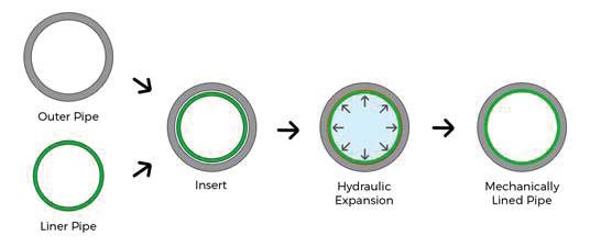
Mechanically lined pipes (MLPs) integrate the corrosion resistance of a CRA liner with the strength of a carbon steel outer pipe. The manufacturing process begins by fabricating the CRA liner, typically made from materials such as 825 or 316L, and carefully inserting it into the carbon steel pipe (Figure 1). The composite pipe then undergoes hydraulic expansion. During this step, the carbon steel remains elastic while the CRA liner plastically deforms. Upon releasing hydraulic pressure, the carbon steel’s elastic recovery compresses the liner, forming a secure mechanical bond. To enhance durability, a corrosion-resistant weld overlay is applied to the pipe ends, extending the CRA layer and ensuring continuous corrosion protection across joints. This step minimizes joint-related risks and enhances long-term reliability. MLPs are efficient, requiring significantly less CRA material than CRA-clad or solid CRA pipes, thereby reducing costs. Additionally, shorter manufacturing lead times make MLPs ideal for projects with tight schedules. The process is environmentally sustainable, generating up to 50% less CO₂ compared to CRA-clad pipe production.
Sustainability: CRA-Lined Pipes vs. CRA-Clad Pipes
CRA-lined pipes offer substantial environmental advantages over CRA-clad pipes, positioning them as a more sustainable option. The mechanical bonding process used in CRA-lined pipes eliminates the need for energy-intensive high-temperature metallurgical bonding, thereby significantly reducing energy consumption and CO₂ emissions. Additionally, CRA-lined pipes achieve the same corrosion resistance while using considerably less CRA material, which lowers their overall carbon footprint compared to CRA-clad pipes. In terms of recyclability, CRA-lined pipes excel. The mechanical bond allows for the straightforward separation of the CRA liner from the carbon steel backing at the end of their service life, enabling both materials to be recycled independently. By contrast, the metallurgical bond in CRA-clad pipes complicates separation, reducing recycling efficiency and increasing processing costs. These features make CRA-lined pipes more energy-efficient in manufacturing and better suited for sustainable material management practices, supporting global efforts to reduce waste and foster a circular economy.
Testing overview and results
The pipes were 12-meter sections of API X60 carbon steel with a 22.23 mm wall thickness and CRA liners of 2.5 mm or 4.0 mm. A girth weld at the midpoint of each string replicated real-world S-lay installation scenarios.
Coating Simulations and Thermal Effects
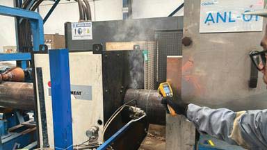
Coating simulations, conducted at 240°C ± 10°C, replicated thermal cycles typical of coating yard operations before the pipes are sent offshore, as shown in Figure 2. These simulations permanently reduced the gripping force between the liner and carbon steel. However, hydrotesting has been shown to partially restore the gripping force, ensuring mechanical integrity under operational pressures. This step enabled a realistic evaluation of mechanical performance after coating and hydrotesting. Figure 1 illustrates the setup used for these coating simulations.
Four-point full-scale bending tests
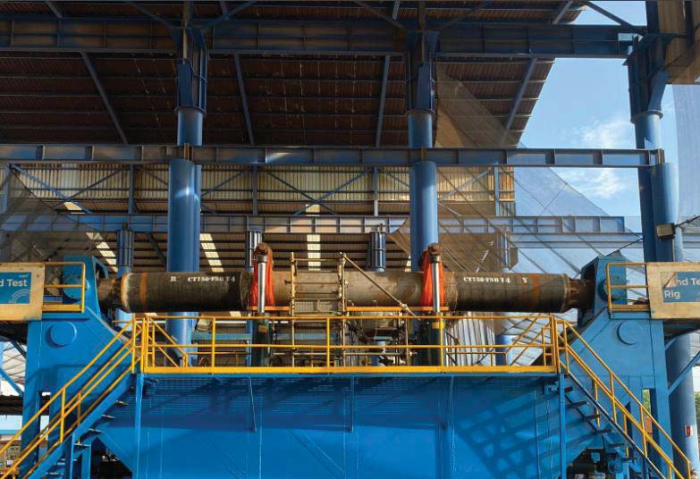
After completing coating simulations, the test strings were subjected to bending tests that closely simulated offshore installation and operational conditions, as illustrated in Figure 3. Each bending cycle involved loading the pipe to a target strain, then flipping it such that the section previously at the 6 o’clock position was rotated to the 12 o’clock position, and vice versa. This process was repeated for three full cycles (a full cycle comprising two loading steps, with six half cycles in total). This approach evaluated the mechanical performance of the 32-inch CRA-lined pipes under realistic installation / operational scenarios.
Strain gauges (SG) and displacement transducers (WD), as shown in Figure 4, were positioned near critical areas, such as girth welds and triple points, to monitor strain and displacement. This setup captured detailed data on pipe deformation and stress distribution, providing insights into the robustness of the CRA-lined pipes under installation/operational conditions.
Performance of configurations
The performance of the configurations was summarized as follows:
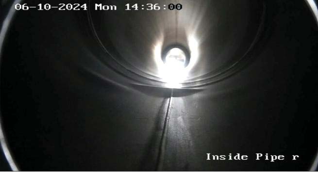
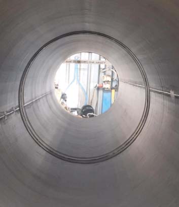
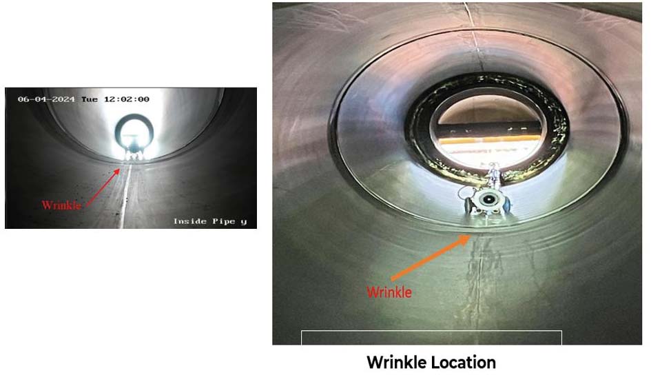
- T1: A 2.5 mm CRA liner experienced localized wrinkling under the highest test conditions (Figure 5). Post-bending hydrotesting at 216 bar successfully eliminated all wrinkles, restoring liner integrity (Figure 6).
- T2: A 2.5 mm CRA liner showed no wrinkling after bending.
- T3: A 4 mm CRA liner displayed excellent mechanical performance, with no wrinkling or liner separation observed during testing.
- T4: A 4 mm CRA liner demonstrated strong resilience during bending cycles (Figures 7). Wrinkling occurred only under extended testing at higher strains, and hydrotesting reduced wrinkle heights significantly (Figures 8).

Performance against DNV wrinkling thresholds
The mechanical performance of the tested pipes exceeded industry standards under installation/operational conditions, as summarized in Table 1.These results confirm that the tested CRA-lined pipes maintain mechanical robustness under high-strain conditions, making them well-suited for challenging offshore applications. The data also emphasizes the need for careful consideration of strain thresholds when selecting pipe configurations for specific operational environments.

Hi/Lo welding challenges in CRA-Clad vs. CRA-lined pipes
The challenges of Hi/Lo alignment during welding significantly impact the mechanical performance and reliability of welded joints. This is especially critical for large-diameter CRA-clad and CRA-lined pipes. CRA-clad pipes utilize a metallurgical bond between the CRA-clad pipes utilize a metallurgical bond between the CRA layer and the carbon steel backing, while CRA-MLPs employ a mechanical bond. Both configurations ensure robust durability under high-pressure and sour service conditions. However, the metallurgical bond demands precise alignment and heat control at girth welds. Misalignment can lead to stress concentrators, increasing the risk of fatigue and stress corrosion cracking (SCC). Addressing these issues often involves excessive grinding, which risks exposing the carbon steel backing to corrosion, escalating fabrication time and costs.
In contrast, CRA-lined pipes (CRA-MLP) use a mechanical bond, which simplifies pipe fabrication but does not inherently address alignment issues during welding. However, the application of weld overlay at the pipe ends ensures consistent corrosion protection and helps mitigate alignment challenges by providing a uniform and weldable surface. Advanced bonding techniques, precise liner expansion methods, and stringent quality controls minimize the risk of liner wrinkling, which can occur during high-strain installations. Additionally, the mechanical bond minimizes the risk of liner movement during bending or thermal cycles, ensuring structural integrity and reducing the likelihood of operational issues.
For large-diameter applications, CRA-lined pipes provide a streamlined solution that balances flexibility, reliability, and reduced fabrication complexity. Their adaptability to advanced welding techniques and high-strain conditions makes them particularly suitable for demanding offshore and subsea pipeline projects, where cost efficiency and long-term structural integrity are essential.
Opportunities in scaling MLP technology & industry impact
The successful testing of 32-inch CRA-lined pipes represents a transformative advancement in mechanically lined pipe (MLP) technology, overcoming historical limitations in diameter scalability. Scaling MLPs beyond the traditional 6–24-inch range was previously constrained by the reliance on compressive stresses to bond the CRA liner to the carbon steel pipe, increasing the risk of wrinkling or liner deformation under high strain, particularly during demanding offshore installations.
This achievement demonstrates the structural integrity and operational reliability of 32-inch MLPs, establishing them as a cost-effective alternative to CRA-clad pipes for large-diameter projects. By expanding the feasible diameter range, MLPs can now address a broader scope of applications in offshore and subsea environments, including essential sectors such as carbon capture, utilization, and storage (CCUS).

CRA-lined MLPs effectively combine corrosion resistance with significantly reduced production costs, offering notable savings in capital expenditures (CAPEX) for pipeline projects. The traditionally high costs of CRA-clad pipes have often acted as a barrier to development, stalling many potential projects. This advancement provides a financially viable solution, unlocking these projects and enabling progress. Additionally, the reduced use of costly CRA materials, faster production timelines, and lower CO₂ emissions make MLPs both environmentally sustainable and economically attractive. The successful testing of 32-inch CRA-lined pipes not only validates their mechanical performance under challenging conditions but also underscores their role in modernizing pipeline infrastructure. By addressing stringent performance requirements, MLPs offer a proven solution for transporting corrosive fluids under demanding offshore conditions.
This development enhances the competitiveness of MLPs in industries like CCUS, ensuring they meet the evolving demands for cost-effective, reliable, and sustainable pipeline solutions. This breakthrough solidifi es MLPs as a key technology in advancing global energy initiatives and shaping a more sustainable future for pipeline infrastructure.
About this Tech Article
Appearing in the February 2025 issue of Stainless Steel World Magazine, this technical article is just one of many insightful articles we publish. Subscribe today to receive 10 issues a year, available monthly in print and digital formats. – SUBSCRIPTIONS TO OUR DIGITAL VERSION ARE NOW FREE.
Every week we share a new technical articles with our Stainless Steel community. Join us and let’s share your technical articles on Stainless Steel World online and in print.